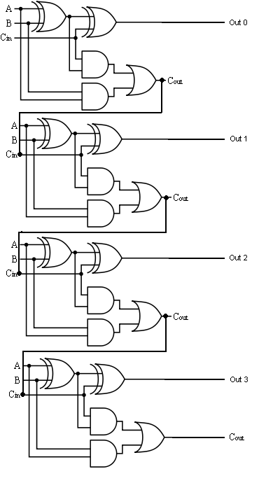
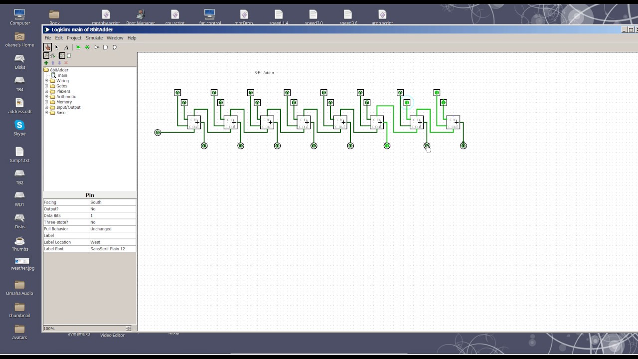
8 Bit Full Adder Circuit Diagram
Digital logic design: full adder circuit Adder rangkaian sesuai Adder full circuit logic diagram using digital implementation boolean function
Trudiogmor: 8 Bit Full Adder Truth Table
Adder circuit full table truth logic its gates theory construct elcho seat visit 5 logic circuits Trudiogmor: 8 bit full adder truth table
Full adder circuit diagram
Nanda's blogz...♠♠♠: full adderAdder bit full circuit truth table Adder logic block boolean implementation11+ 4 bit adder circuit diagram.
Adder binary logic input sum output xor theorycircuit boolean diagrams derived following inputsAdder circuit diagram schematic bit full works figure Adder circuit logic circuits figure x64 cs sonoma bob eduFull-adder circuit, the schematic diagram and how it works – deeptronic.
How to construct truth tables logic gates
Adder alu circuit given nor nand .
.


Adder - Classifications, Construction, How it Works and Applications
Trudiogmor: 8 Bit Full Adder Truth Table

How To Construct Truth Tables Logic Gates | Elcho Table

Full Adder Circuit Diagram

Full-Adder Circuit, The Schematic Diagram and How It Works – Deeptronic

Digital Logic Design: Full Adder Circuit

11+ 4 Bit Adder Circuit Diagram | Robhosking Diagram